Informed Design BIM definition workflow - model orientation
Learn how to use Behavior Type to specify the host object in Revit, and use the UCS, Insertion point, and Placement plane commands to control the orientation of the loadable Revit family (RFA) for insertion into a Revit project model.
Step-by-step guide
Manage the orientation and placement of a product before inserting it into Revit by using the Informed Design BIM definition workflow in Inventor.
Manufacturing CAD software often defaults to modeling with the Y-axis vertical, and BIM software often defaults to modeling with the Z-axis vertical. To address this discrepancy, use the Family Definition tools in the Informed Design BIM Definition workflow to control the orientation and placement of a Revit family.
User Coordinate System (UCS)
First, it is important to understand how to reorient a model using the UCS option in the family definition.
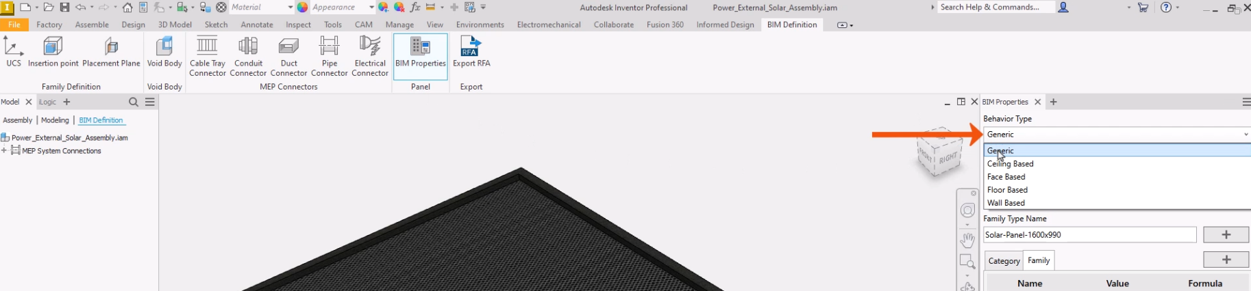
- With the model open in Inventor and the BIM Definition tab active, click BIM Properties.
- In the BIM Properties panel, set the Behavior Type to Generic.
In this example, the Inventor design has been modeled with the Y-axis vertical. Use the User Coordinate System (UCS) command to ensure that the Z axis will be vertical when the generated family is placed into Revit.
- On the ribbon, click BIM Properties to close the panel.
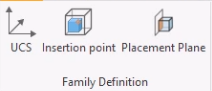
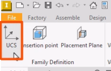
- In the Family Definition panel, click UCS.
The UCS is positioned relative to the origin of the assembly.
- Use the cursor to move the UCS, and then click to place it.
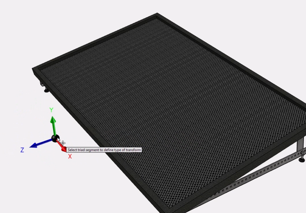
- Alternatively, type in the exact coordinates for the UCS.
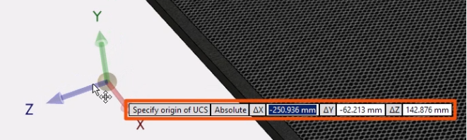
Once the UCS is positioned, the command remains active, and the UCS can be moved along an axis or rotated as needed.
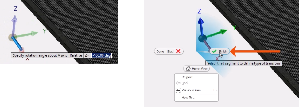
- Rotate the UCS until the Z-axis is vertical.
- To place the UCS, right-click and select Finish.
On placement of the UCS, parameters are created that can be used to control the UCS position and rotation.
- Open the Parameters dialog box.
- In this case, for parameter d84, change the Equation value to 90.
- For parameters d81, d82, and d83, adjust the Equation values to 0.
Notice that the UCS position changes as the adjustments are made.
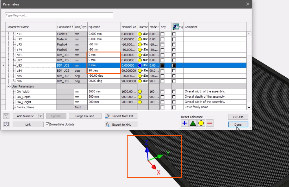
- Click Done.
The UCS appears in the BIM Definition browser and is named BIM_UCS. Only one BIM UCS can be included in a product definition.
- To edit the BIM UCS, right-click it and select Redefine Feature or Delete.
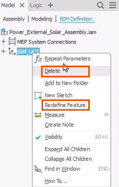
The BIM UCS is used to define the orientation of models with the generic behavior type. Only the Z orientation of the UCS is relevant; the position is ignored. The UCS is independent and has no relationship with any insertion point or placement plane.
Placement Plane
Consider a more complex example. In this case, the goal is to publish a family that can only be placed on a Revit host object of a specific category.
A placement plane is required for models with any Behavior Type other than Generic. Face Based, Wall, Floor, and Ceiling behavior types are known as hosts. Hosted Revit families can only be placed on an object of the host category in a Revit project. For example, ceiling-hosted objects can only be placed on ceilings, while face-based families can be placed on the face of any host.
To set a placement plane for a Face Based family:
- On the BIM Definition tab, click BIM Properties.
- In the BIM Properties panel, for Behavior Type, select Face Based.
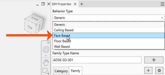
The Placement Plane command starts automatically.
- In the browser, hover the cursor over each work plane to preview the orientation.
- Click a plane to select it, such as the XZ Plane.
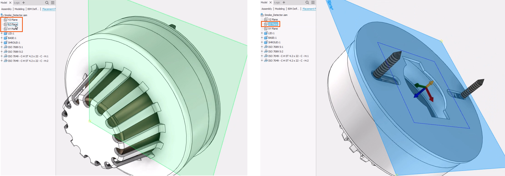
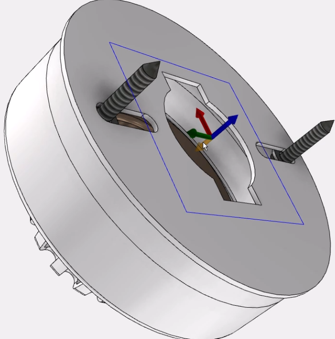
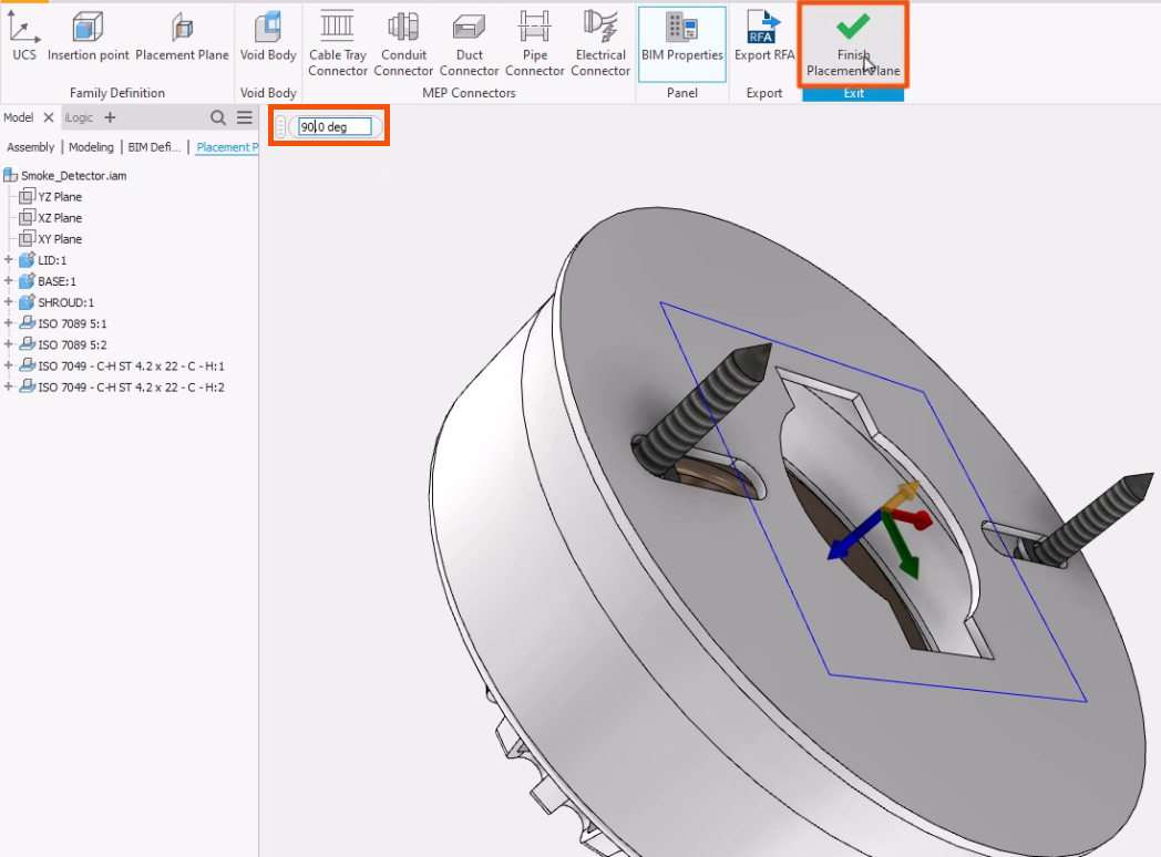
Once a placement plane is selected, the blue UCS arrow faces away from the host.
- Click the shorter yellow arrow to flip the UCS direction.
- Enter a value in the degree input box, such as 90, to change the angle of the UCS.
- On the ribbon, click Finish Placement Plane.
- Reopen the BIM Definition browser, where the BIM Placement Plane now displays.
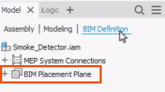
- To edit the BIM Placement Plane, right-click it and select an option.
Insertion Point
Defining an insert point is optional. By default, the Inventor origin (0,0,0) is used as the insert point for a Revit family.
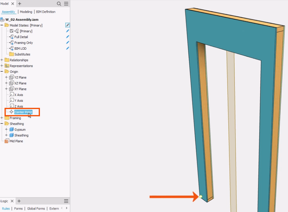
- In the model browser, under Origin, select Center Point to see the default insert point highlighted in the preview.
The insert point is independent of any included BIM UCS and will automatically be projected onto any included placement plane.
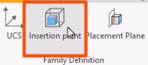
- To add an insert point, in the Family Definition panel, click Insertion point.
- Use the standard Inventor workflow to define the insertion point.
- If needed, right-click and select Cancel to complete the command.
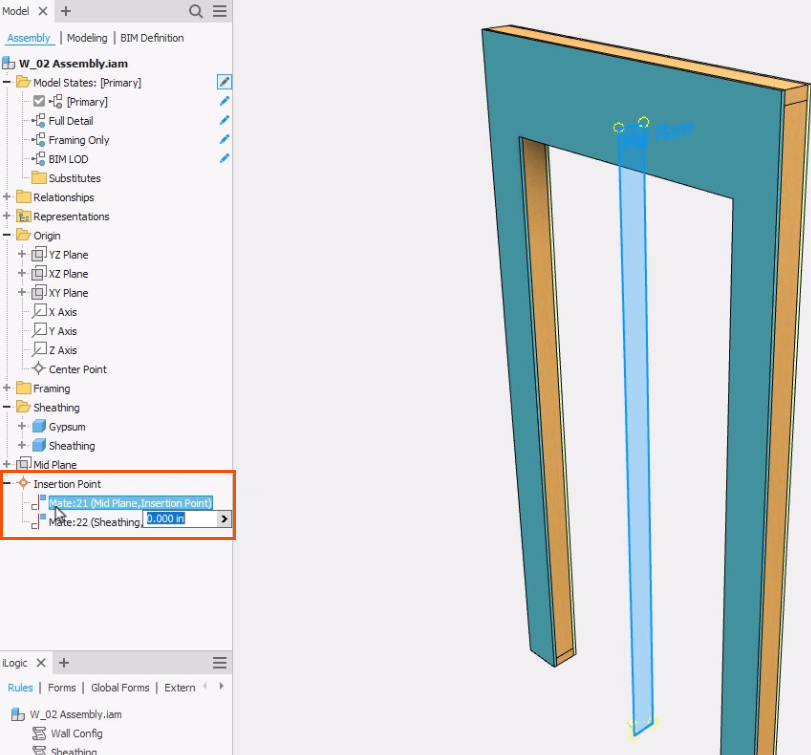
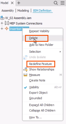
Once the new insertion point is defined, it displays in the BIM Definition browser.
- To edit the insertion point, right-click it and choose Redefine Feature or Delete.
On creation, parameters are added to the model that can be used to control the position of the insert point. Only one insert point can be included in the BIM definition.
- Back on the Assembly tab of the browser, expand Insertion Point to select and view a point in the model.